Connall De Silva
Problem Statement
For this project my target problem is the lack of monitoring water levels for personal consumption when the water is stored in containers out of direct eye contact.
During long hikes, it is essential to know your ration levels and water intake rate in order to prevent running out before the chance to replenish. To save time and energy, hikers will often store water in bags and pouches located within their backpack with a tube that travels from the inside the bag over the shoulder strap close to the mouth. Thus allowing for consumption without the need to stop, take off the bag and pull out a water bottle. One issue with this is that users do not have a quantifiable means to know how much water is in reserve. Determining water level using weight is not accurate as most of the weight is supported by the lower back rather than shoulders.
Project Goals
My goal for this project is to create a prototype that will track water levels and display this information in a easy to understand, quantifiable manner.
To achieve these goals I explored different types of methods to measure water levels using pressure sensors, float sensor and non contact liquid sensors. The means to display the data for this prototype is visual with future plans to integrate haptics, signaling when the water level has dropped below a certain point.
Initial Changes
After a consultation with the Professor and TAs I pivoted from using a pressure sensor to non contact fluid sensor to be mounted outside of the water container.
Another idea that was mentioned and utilized was to move the output from shoulder strap of bag to a wrist band like wearable and for further interaction try to implement some haptic feedback to activate when the water level drops.
Why not implement the vibration motor?
I Do not have the required parts to intergrade it
Time to acquire parts exceeds the time budget allocated to this project (parts wont arrive in time)
Future Goals
- Use a vibration motor close to skin contact to eliminate the need to have the device in visible range.
- Change the style of casing for wrist band to make it slimmer and lighter
- Alternatively convert the wrist band into a phone app that uses the built in hardware of speaker, vibration motor and led.
- Use multiple non contact sensors to create an array to monitor many different levels of water and showing the results in a way that is similar to a fuel tank gauge.
Affordances
Convenience
By using a non-contact fluid sensor, there is no need to physically interact with the water bottle, which makes it more convenient for the user. Additionally, the fact that the sensor is mounted on the outside of the bottle means that it can be easily accessed without having to remove the bottle from the bag.
Efficiency
The non-contact sensor can detect the presence or absence of water without coming into contact with the fluid, which can help to prevent spills or leaks. This makes it more efficient and less messy than traditional methods of checking water levels.
Accuracy
The non-contact fluid sensor can provide a more accurate reading of the water level than simply eyeballing it, which can help to prevent dehydration or overhydration.
Portability
The fact that the LED is located on a wristband means that it is easily portable, and the user can be alerted to low water levels even if they are not looking directly at the bottle.
T3 Cube
Temporal synchrony
3 - Getting the info in real time allows for a solid midpoint on the temporal synchrony. Only slightly behind seeing the water level yourself.
Spatial topological synchrony
2 - It give a single notification that does not show exact level of water remaining. It gives a different type of feedback in the form of blinking led instead of image of water or simulation of weight
Mutual knowledge
3 - The device shows an understanding of water level that the users sets before hand. Therefore there is a mix of real life experience of where the user determines where to place the sensor and learned knowledge for setting up the product
Process
Soft Wiring
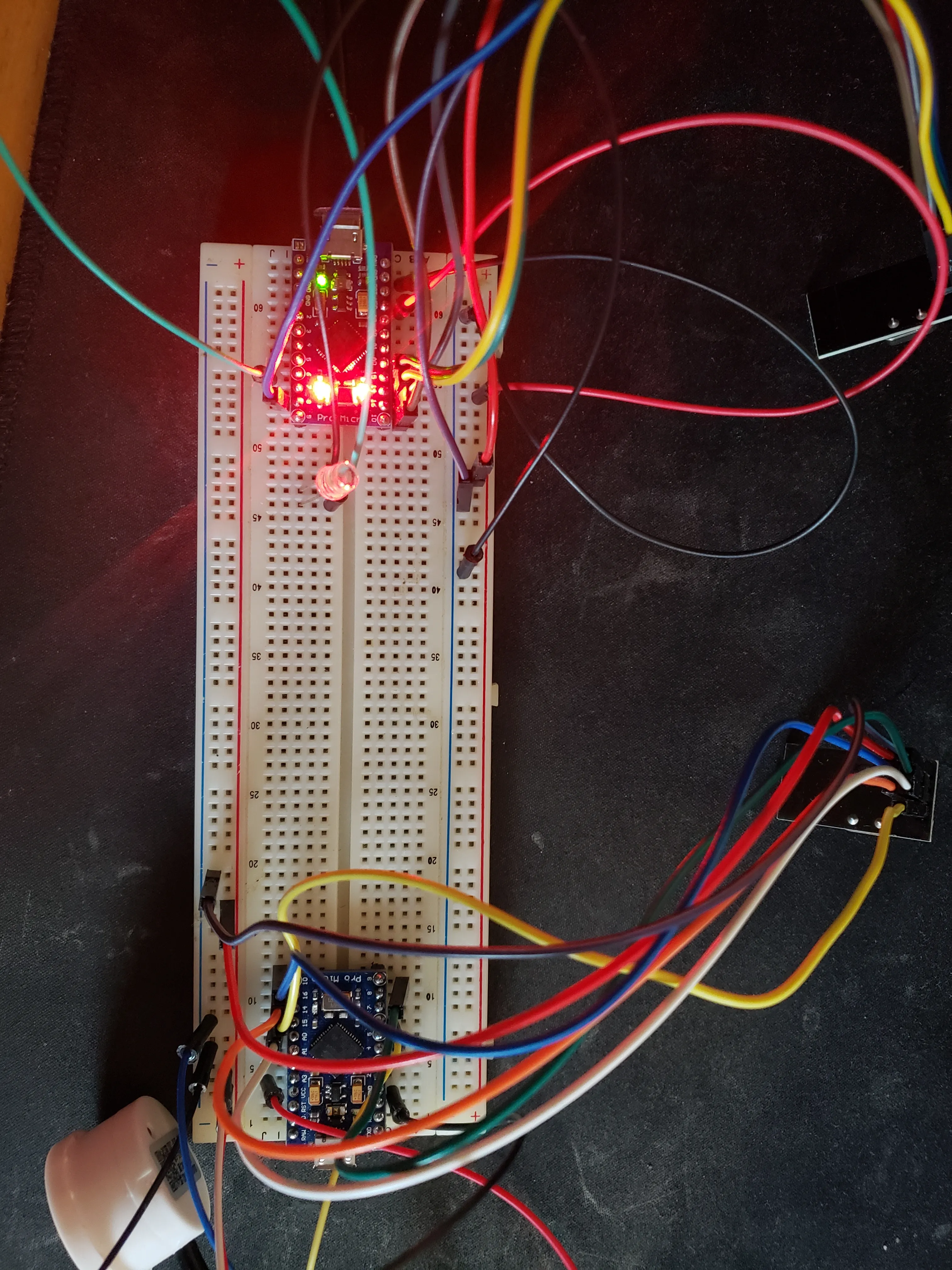
First Wiring Prototype
2 separate Arduino micros on a single breadboard with each connected to a NRF24L01 module. One micro is wired to the non contact fluid sensor, the other wired to an LED.
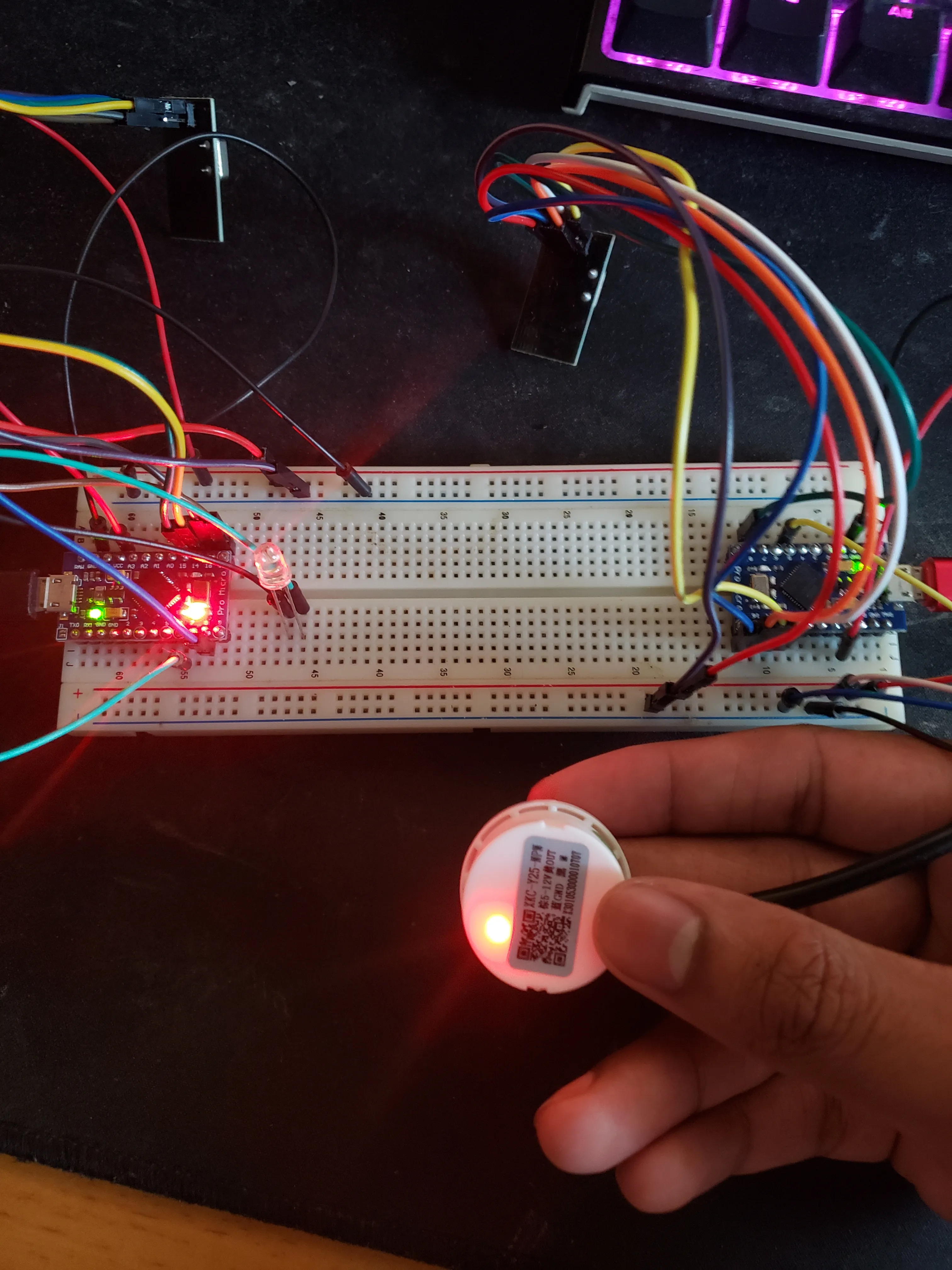
Simulating full water
Finger on the non contact fluid sensor shows that the led on the other micro is off, therefor simulating that the water level is above the sensor.
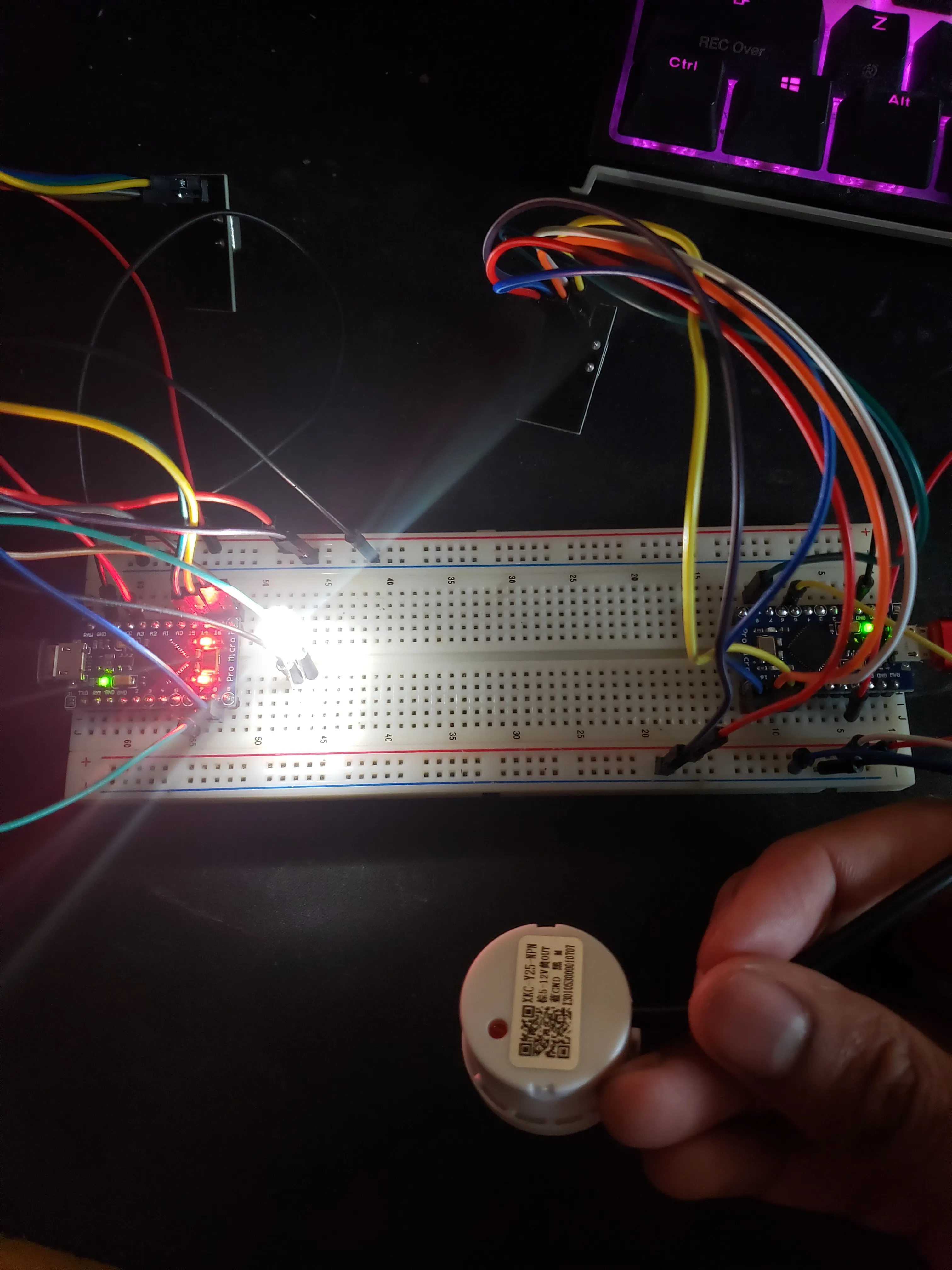
Simulating no water
Nothing over the non contact fluid sensor shows that the led on the other micro is on, therefor simulating that the water level is below the sensor.
Design Process
Code
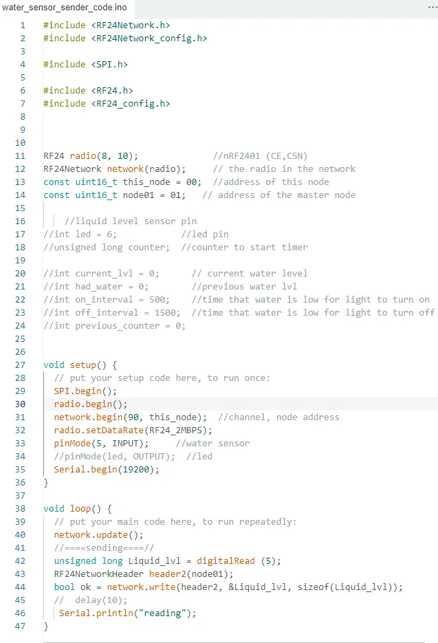
Code for the module that has the fluid sensor
This code stores the fluid sensor data in a variable and the sends it to the other module only if they both connect to the same internal network.
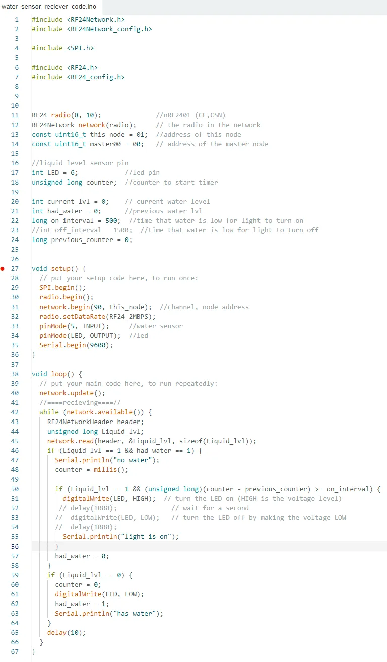
Code for the module with the led
This code receives the fluid sensor data variable and executes the loop that checks if the reading is high or low. when low it turns on the led. this is only if they both connect to the same internal network.
3D Modeling
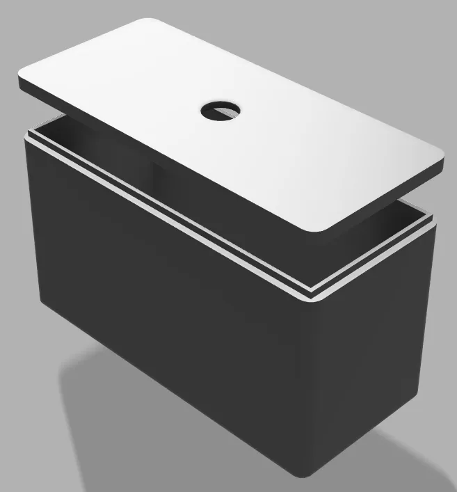
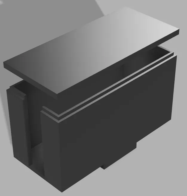
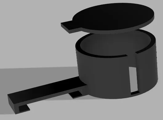
Receiving module case
3D model of receiving module that holds the led made in Fusion 360. With snap on lid with a whole for the led head to pop out.
Sending module case
3D model of sending module that attaches to the fluid sensor made in Fusion 360
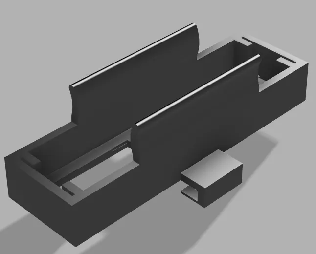
Battery holder
3D model of battery holder made in Fusion 360. clips on the bottom to slide over Velcro and elastic bands
Fluid sensor case
3D model of fluid sensor case that attaches to the sender module made in Fusion 360